For this assignment, we were tasked with presenting a cartesian motion system that has 2.5 degrees of freedom. We decided to present this a claw machine.
We were provided an Arduino Mega, two types of step motors, pulleys that are attached to the step motors, belts, square steel extrusion bars, and a SolidWorks file of a slider that is compatible with the steel bars. All other parts must be designed by us and made using either a 3D printer or a laser cutter. We were also allowed to use standard fasteners to connect our parts, but not temporary solutions like glue and tape. From these boundaries, we created our system.
We first brainstormed ideas for our system and sketched how they would work. Our first design was for a mini golf course. We decided later on that a claw machine would be more fun and demonstrate our knowledge much better.


We first brainstormed ideas for our system and sketched how they would work. Our first design was for a mini golf course. We decided later on that a claw machine would be more fun and demonstrate our knowledge much better. We also sketched out the actual system and how it would move. There were many ways we could've created this system and it could have been used for multiple different purposes.
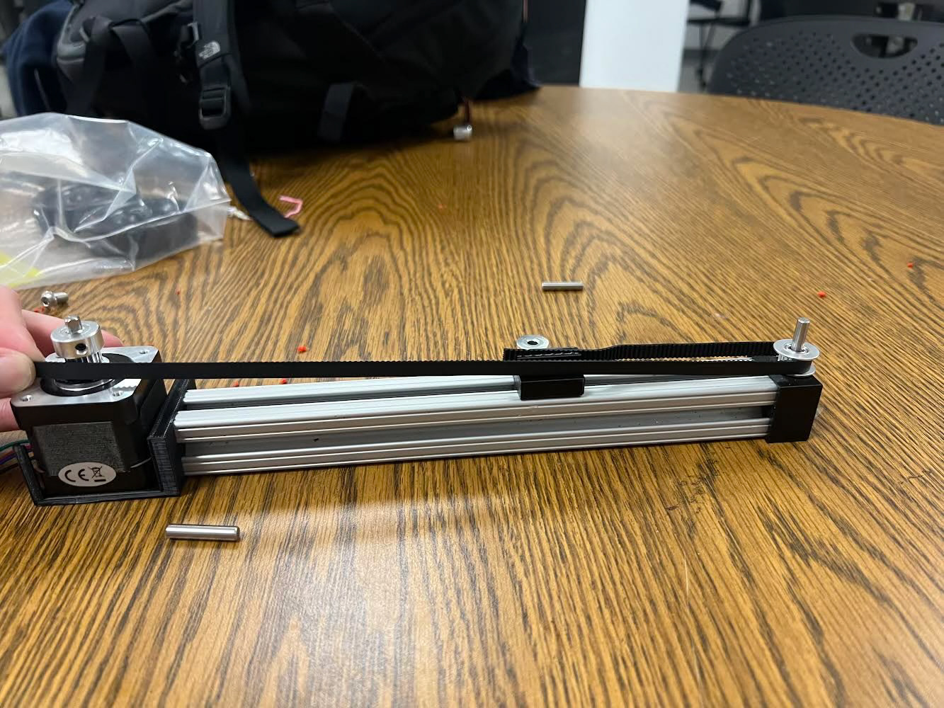
We then moved on to prototyping. We first 3D printed a holder for the step motor and bar, a slider with ridges for a belt to be put in, and a holder for the end of the bar with a hole to add an axel and pulley. We connected the motor to an Arduino Mega and using Repetier Host, we successful moved the slider. We then based the rest of our design on this prototype.
We cadded all the parts we need for our system using SolidWorks. We made sure all of our measurements were accurate and that all the parts that need to be screwed into the bars were able to be. We found that the 3D prints didn't come out very accurate and we had to make a lot of modifications after the fact. Some of the prints ended up breaking as well, and because we were running out of time, we tried gluing the parts, but it didn't work. I discovered that using a soldering iron, you can melt both pieces that need to be attached and connect them. It created a stronger connection then before it was broken. This worked out very well for us.
We had a lot of trouble getting the system to work constantly caused by stability issues with the base board, badly cut bars, and delays between the motors movement. We used a combination of code, sanding, and soldering to get the system to work very constantly and get the sliders to move smoothly at the same time.
I was in specifically in charge of the claw. For this, I cadded a slider that can hold a toy motor. This would turn the string that held the claw and allow it up and down. For the claw, I made a cutout for a toy step motor and another cut out for an axel. The actual claw was two gears with hooks sticking out of it. One fit on the toy motor and the other fit on the axel. When the motor turned, the gears would move either inwards or outwards. The main issue with my design was the toy step motor. It's not very strong which cause the lowering and raising mechanism very slow. It also did not generate much torque which made the clamping mechanism very weak. The reason they were used was for size and weight because if the claw and slider was too heavy, it would not move smoothly. In the future, I'd use different step motors, and make the slider stronger and have more structure to allow for use of the different step motors.
Even with these problems, we were able to design a functioning claw machine. This was a great learning experience from making a system with multiple motors to using new coding software. I also learned that prototyping is constant volatile process. Sometimes your design works, sometimes it doesn't. But ever success or failure is another thing you learned.